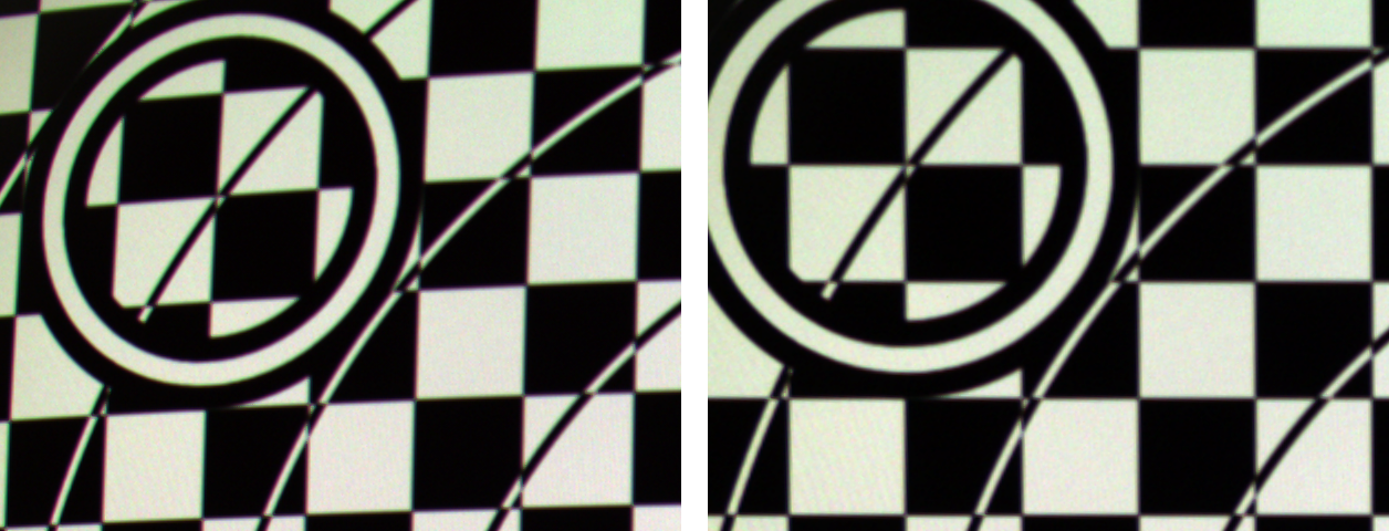
Camera 2.0
-- Zero Geometry Distortion, Zero Chromatic Aberration
-- Distortion-free Camera Calibration
- Scene will be imaged on sensor via camera lens.
- Virtual Window is between scene and camera and contains Virtual Sensor and Virtual Monitor.
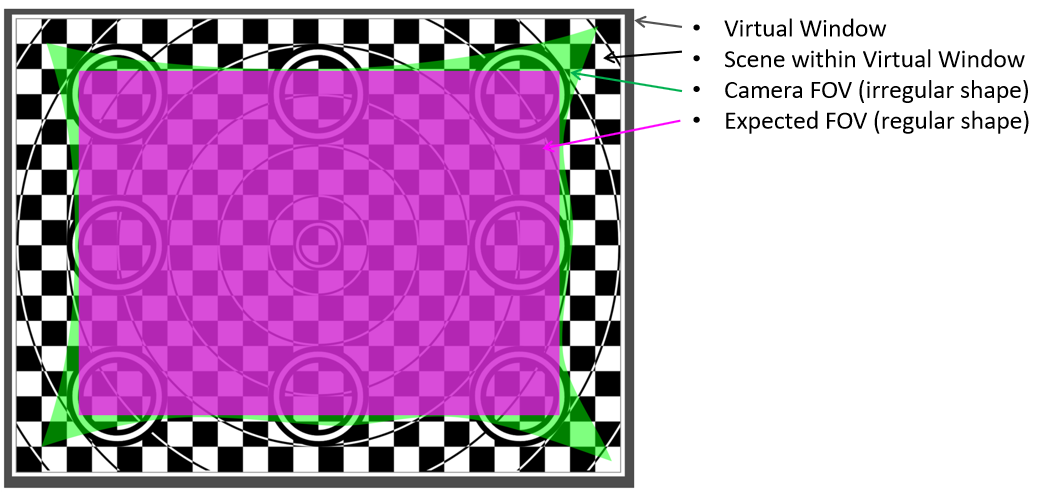
- Lens causes uneven distribution of View Points on Virtual Window to get an Irregular FOV (green).
- Root cause of Image Distortion: to display an irregular FOV on a regular shaped display device.
- Virtual Window is between scene and the camera and contains Virtual Sensor and Virtual Monitor.
- The irregular shaped FOV (green) will be imaged on the sensor.
- A regular shaped FOV (Magenta) can be cropped from the green FOV and a Virtual Sensor can be constructed.
- Image FOV Crop makes Physical Camera a Virtual Camera within the Virtual Window.
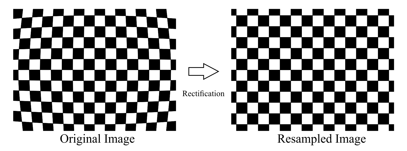
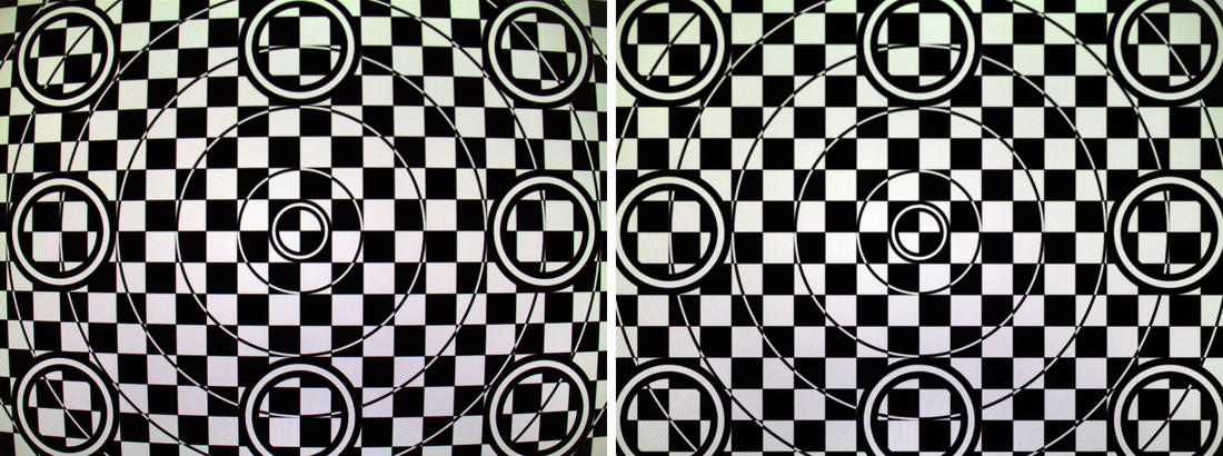
- The Virtual Image is always Distortion-Free.
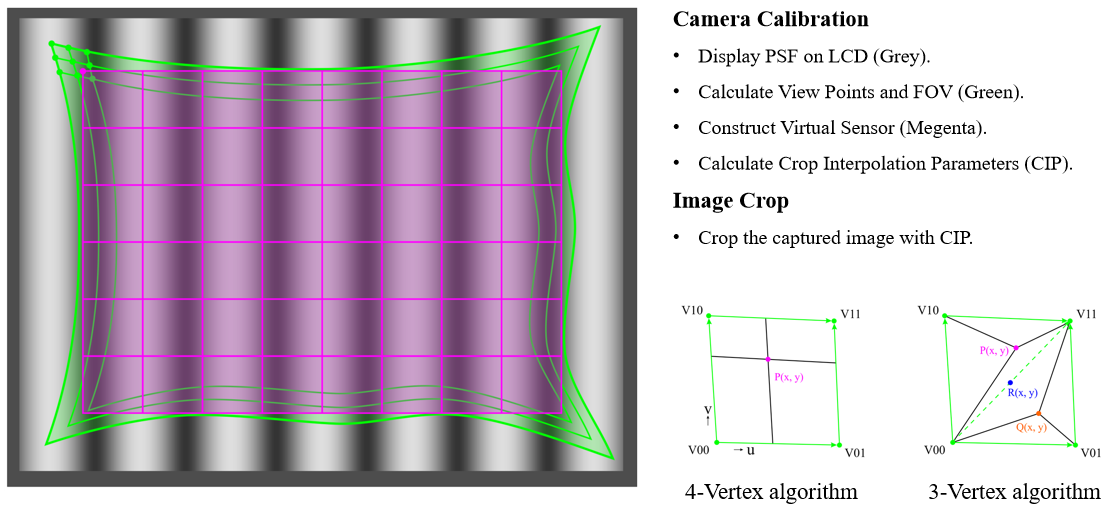
The calculation of Image Crop Parameter (ICP):
- The brightness of each point within a 4-Vertex Arbitrary Quadrilateral is determined by the brightness of the 4 vertices.
- The brightness of each point within a 3-Vertex triangle is determined by the brightness of the 3 vertices.
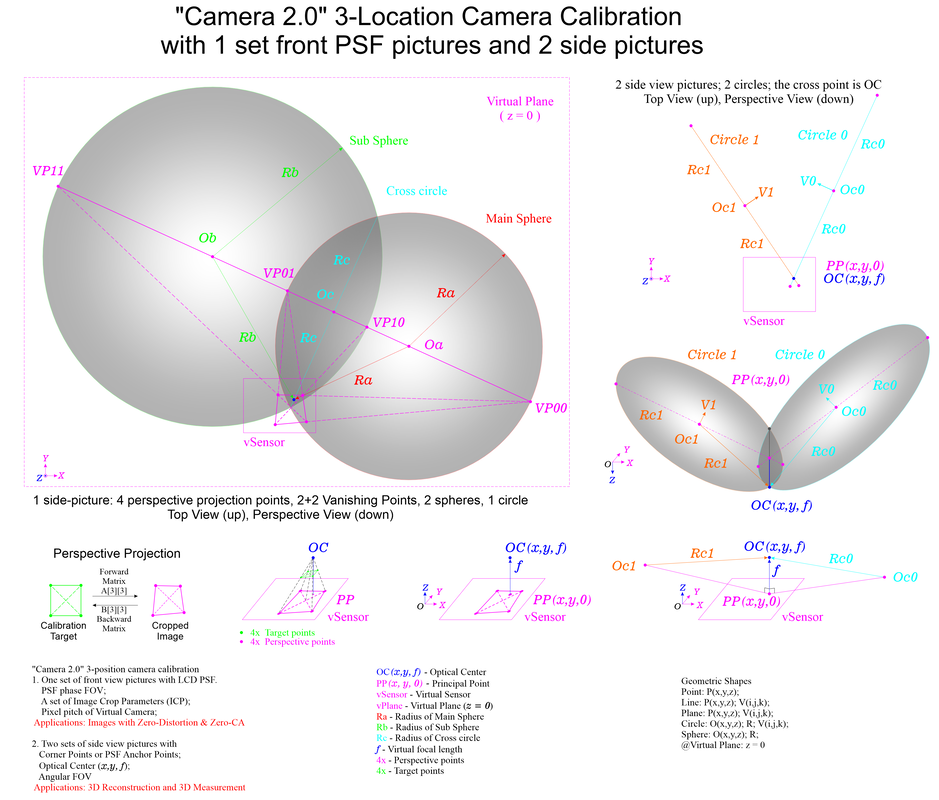
The optical center (OC) of the virtual camera can be obtained by taking another 2 side view pictures or PSF images. The calibration target can be the same LCD panel for the front view 2D calibration, or a smartphone, or a chessboard, etc.
For any square on the target, the 4 vertex points will be shown as an arbitrary quadrilateral (AQ) on the cropped camera image. If the 2 pair of the opposite sides are not parallel, they will be convergent to 2 vanishing points (VP) on the image plane. The 2 VPs form a line (VPL). With the 2 VP points as the diameter, a sphere (Main Vanishing Sphere, MVS) can be formed. The OC will be on this sphere. For the same AQ, the 2 pair of the opposite vertices' cross lines can be extended to intersect with the VPL to obtain another 2 VPs. With the 2 VP points as the diameter, the second sphere (Sub Vanishing Sphere, SVS) can be formed. The OC will also be on this sphere. The 2 spheres will intersect to form a circle (Vanishing Circle, VC). The OC will be on the VC. One side view picture can get one VC. Another picture can get the second VC. The 2 VCs will intersect on 2 points. The OC is the point on the camera side.
For geometric shapes in the world coordinate system (WCS), a sphere can be represented by 4 values: one center Sphere(x, y, z), one radius Sphere_R. A circle can be represented by 7 values: one center Circle(x,y,z), one normal vector of the circle plane Circle(i,j,k), one radius Circle_R. From the 4 perspective projection points of a picture, 2 vanishing spheres and 1 vanishing circle can be obtained. All the centers are on the virtual plane, z = 0. For all the vectors, k = 0. For the 2 vanishing circles, the 2 diameter lines on the virtual plane will intersect at the principal point PP(x,y,0) of the virtual camera. The optical center is OC(x,y,f). The virtual focal length f can be calculated by Pythagorean theorem. Where the distance from PP to one Circle(x,y,z) is one right angle side, the Circle_R is the hypotenuse, the virtual focal length f is the other right angle side, as shown by the picture below.
With the LCD panel and the camera at the front view location and one set of PSF pictures, the 2D calibration can get a set of ICP, 2D-FOV and the pixel pitch. With another 2 side view pictures, the 3D calibration can get the 3D Angular-FOV.
 Error-free 3D reconstruction
"Camera 2.0" -- Camera Calibration and Image Crop to get Distortion-Free images and videos
Principle of Camera Calibration:
Color Camera Calibration:
Pixel Ray Vector Calibration:
3D Camera Calibration:
Projector Calibration:
Quasi-Imager Calibration:
Principle of Camera Calibration:
- Optical lens in camera makes the distribution of View Points of sensor pixels uneven on object surface and the FOV shape is irregular.
- The root cause of Image Distortion is trying to display the irregular shaped FOV on a regular shaped Displaying Device.
- An LCD flat panel can be used as Calibration Target.
- Phase Shifting Fringe (PSF) Patterns can be used to encode all the LCD pixels.
- Two fields will be created on the LCD surface: a Uniform Brightness Amplitude Field and a Linear Phase Angle Field.
- Every pixel of the image sensor will be independently illuminated and phase angle encoded by the 2 fields by Physically Interpolation.
- The physical View Point of each sensor pixel on LCD can be determined by its phase angle. The FOV Shape will be Irregular.
- A rectangular shaped FOV and a Virtual Sensor can be created within the camera's FOV on LCD.
- A Virtual Pixel will be within a set of 4 neighboring View Points and a set of Image Crop Parameter (ICP) can be calculated.
- The ICP will be used to resample the Captured Images to get the Distortion-free Images.
Color Camera Calibration:
- For color camera, the View Points of the same pixel of the 3 R-G-B channels are different on LCD.
- The shapes of the 3 FOV will be irregular and different.
- A Common Virtual Sensor will be created within the 3 FOV.
- 3 sets of ICP will be calculated for the 3 R-G-B channels.
- The Cropped Images resampled from the Captured Images will have Zero Geometrical Distortion and Zero Chromatic Aberration.
Pixel Ray Vector Calibration:
- The ray vector of a sensor pixel can be determined if a linear stage is used to set the LCD monitor at 2 or more locations.
- All the pixel ray vectors in space can be calibrated individually, independently and accurately with 0 system error.
3D Camera Calibration:
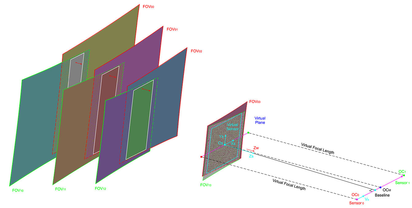
- The pixels ray vectors of the dual-view camera sensors can be determined on space.
- The FOV of each camera can be mapped at any 6-DOF location on space.
- A Common Virtual Plane and a Common Virtual Sensor that meets the requirements of Epipolar Geometry can be created.
- 2 sets of ICP can be calculated for the 2 cameras.
- Pixel Matching and 3D Reconstruction by Triangulation will be conducted within the same lines of the cropped images.
Projector Calibration:
- A projector can be calibrated indirectly by an LCD flat panel via a calibrated camera.
- A set of PSF patterns will be projected by the projector and the camera will as reference device.
- A set of Reverse Crop Parameters (RCP) will be calculated.
- The original images will be reversely cropped by the RCP and be displayed on the projector imager.
- The projected images on screen will be the same as the original images with zero geometrical distortion and zero chromatic aberration.
Quasi-Imager Calibration:
- Any quasi-imaging devices can be calibrated with the approaches similar to the projector calibration.
- PSF patterns will be generated and be projected out by the quasi-imager.
The Ultimate Universal Distortion-free Geometry Calibration
- The opto-electro-mechanically generated geometry quantities have distortions.
- The principle and the technique of "Camera 2.0" can be extended to all similar opto-electro-mechanical apparatus and devices.
- All the geometry quantities can be made distortion-free: 2D images; 3D point clouds; Line-of-Sight grid maps; gimbal space angles.
- Physical or Mathematical Encoding/Decoding Medias: Phase Shifting Fringes etc.
- Geometry Accuracy Transfer Mapping: The accuracy can be transferred from one component to another when appropriate medias can be applied.
- Calibration Chain: LCD/LCoS -> Cameras, image sensors -> Projectors, LoS or Light/Energy directing devices.
- The opto-electro-mechanical apparatuses or devices include: Cameras or any imaging sensors with any type of optical lens optics; Projectors or any imager chips with optical lenses; Light/Energy Directing devices such as galvos, MEMS mirrors, Fast Steering Mirrors; Motors or any components that are driven by electro-magnetic fields and forces; etc.
Other Key Technologies
3D Surface Measurement
Image Stabilization
Advanced Optics and Imaging Sensors
Vibration Measurement System Integration
3D Printer Additive Manufacturing System
Non-destructive Testing/Evaluation/Monitoring
Robot Technology
- 3D cameras (3D scanners) with stereo cameras and pattern engine
- Light engine with multi-spectrum
- Structure light pattern engine with multi space cycles
- Multi-axis 360° 3D surface scanning
- Seamless 3D data stitching
- Real-time 3D surface deformation measurement and monitoring
- High accuracy mechanical system calibration
- In-situ machine tools worn monitoring and compensation
- Product surface quality examination
- Surface geometry modeling
- Non-destructive Evaluation (NDE/NDT/NDM)
Image Stabilization
- 3-Axis Image Stabilization in high dynamic environment
- Moving target monitoring and tracking
- High Energy Light directing and Line-of-Sight Stabilization
Advanced Optics and Imaging Sensors
- Multi-spectrum, multi-ROI image sensors
- Dual Polarized image sensors
- Split-lens image sensors
- Omnidirectional imaging and tracking system
Vibration Measurement System Integration
- High rotating speed object vibration measurement
- 3D vibration measurement for moving object
- Area Vibration 3D Imaging at high frame rate (60 fps)
3D Printer Additive Manufacturing System
- 3D Printers and additive manufacturing
- 3D Printer system calibration and compensation
- In-situ additive manufacture monitoring and compensation
- Rapid prototyping
Non-destructive Testing/Evaluation/Monitoring
- Ultrasonic non-destructive testing and evaluation (NDT&E)
- Electromagnetic wave and eddy current NDT
- Infrastructure NDT&E with 2D Image & 3D surface point cloud
Robot Technology
- Robot control with 3D stereo image sensors
- Intelligent robots
- Harsh environment robots
- Under water robot Inertial Navigation System calibration
- Under water structure damage measurement and evaluation

